Cracking Kubernetes Node Proxy (aka kube-proxy)#
This post analyzes the Kubernetes node proxy model, and provides 5 demo implementations (within couples of lines of code) of the model based on different kernel infrastructures (userspace/iptables/ipvs/tc-ebpf/sock-ebpf).
There are several types of proxies in Kubernetes, and among them is the node proxier, or kube-proxy, which reflects services defined in Kubernetes API on each node and performs simple TCP/UDP/SCTP stream forwarding across a set of backends [1].
This post first analyzes the design behind the node proxier model, then implements our own versions of the proxy with different means; although just toy programs, they work theoretically the same way as the vanilla kube-proxy running inside your K8S cluster - in terms of transparent traffic intercepting, forwarding, load balancing, etc.
With our toy proxiers, applications (whether it’s a host app, or an app running inside a VM/container) on a non-k8s-node (thus not in K8S cluster) can also access K8S services with ClusterIP - note that in Kubernetes’s design, ClusterIP is only accessible within K8S cluster nodes. (In some sense, our toy proxier turns non-k8s-nodes into K8S nodes.)
Code and scripts used in this post: Github.
1. Background knowledge#
Certain background knowledge is needed to understand traffic interception and proxy in Linux kernel.
1.1 Netfilter#
Netfilter is a packet filtering and processing framework inside Linux kernel. Refer to A Deep Dive into Iptables and Netfilter Architecture if you are not familar with it.
Some key points:
All host traffic goes through netfilter framework.
Netfilter ships with 5 hooking points:
PRE_ROUTING、INPUT、FORWARD、OUTPUT、POST_ROUTING.Command line tool
iptablescan be used to dynamically insert filtering rules into hooking points.One can manipulate packets (accept/redirect/drop/modify, etc) by combining various
iptablesrules.
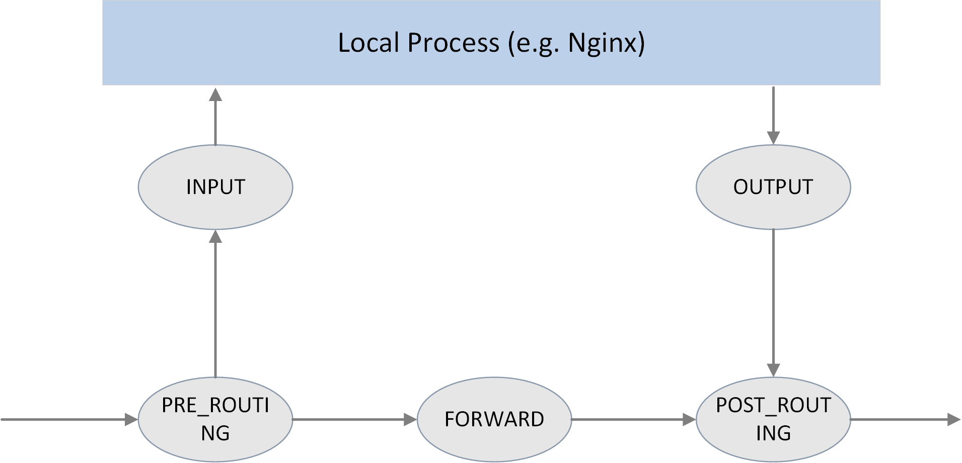
Fig. Five hooking points in the netfilter framework
These hooking points also work collaborativelly with other kernel networking facilities, e.g. kernel routing subsystem.
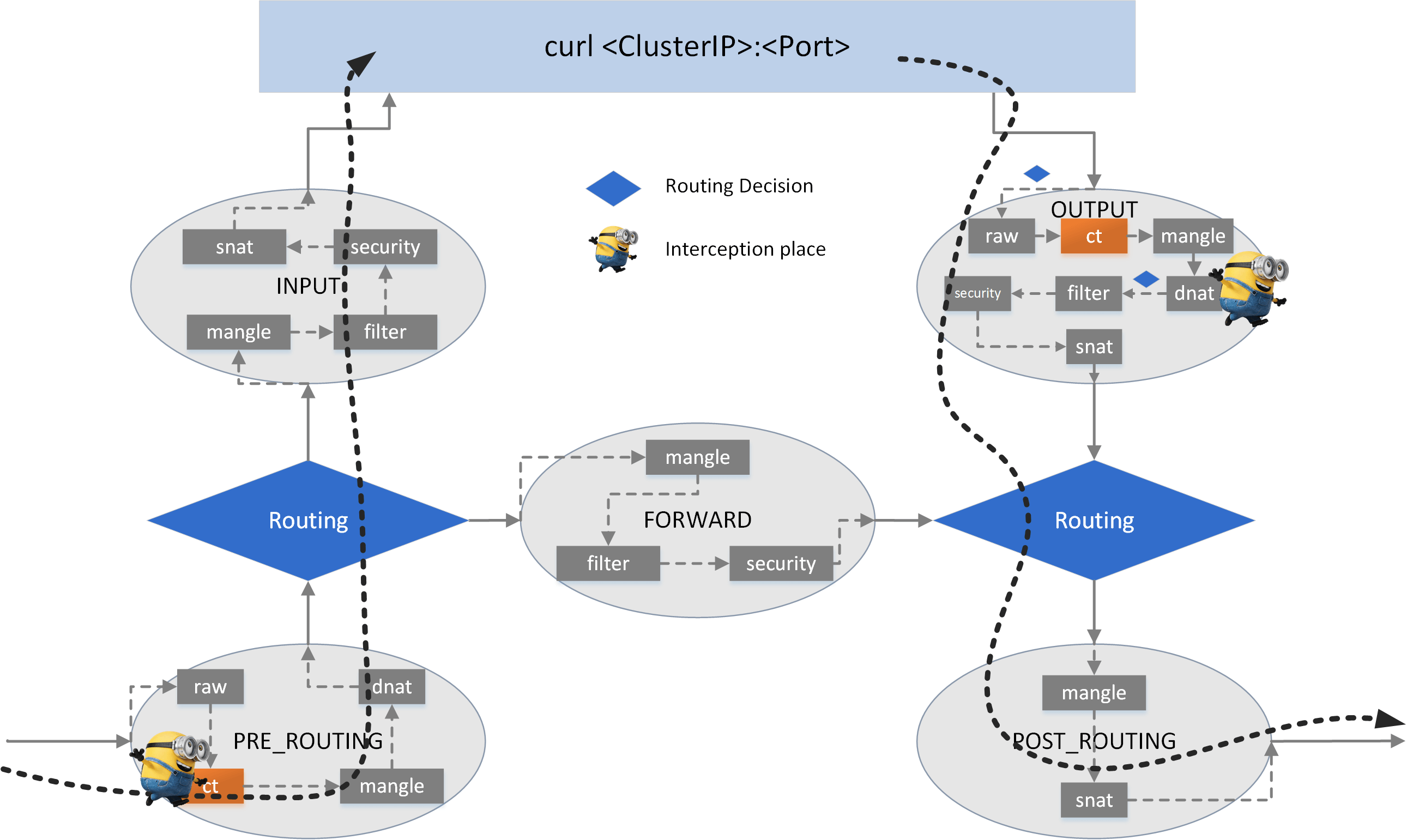
In each hooking point, rules are organized into different chains, each with pre-defined priority. To manage chains by their purposes, chains are further organized into tables. There are 5 tables now:
filter: common filtering, e.g. accept, reject/drop, jump.nat: network address translation, including SNAT (source NAT) and DNAT (destination NAT).mangle: modify packet attributes, e.g. TTL.raw: earliest processing point, special processing before kernel connection tracking (conntrackorCT, also included in the below figure, but this is NOT a chain).security: not covered in this post.
With tables/chains depicted, we get a more fine-grained view:
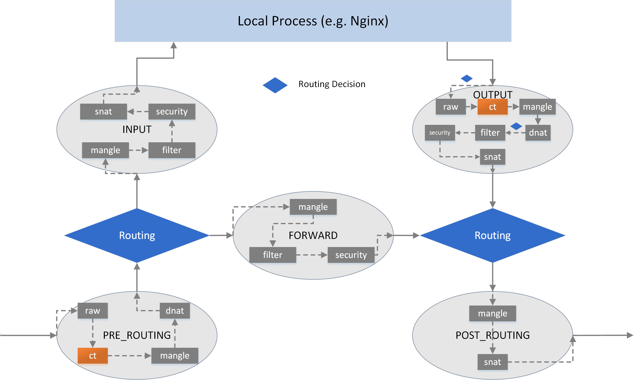
Fig. iptables table/chains inside hook points
1.2 eBPF#
eBPF is another traffic hooking/filtering framework inside Linux kernel. It is more powerful than Netfilter, and is likely to replace the former in the (long long) future.
Refer to How to Make Linux Microservice-Aware with Cilium and eBPF for an introduction.
1.3 VIP and load balancing (LB)#
Virtual IP (IP) hides all backend IPs to a client, decouples the client from backend instances. In this way, backend activities, such as scaling up/down, pulling in/out, will totally be transparent to clients.
VIP always comes with load balancing as it’s responsible for distributing traffic among different backends:
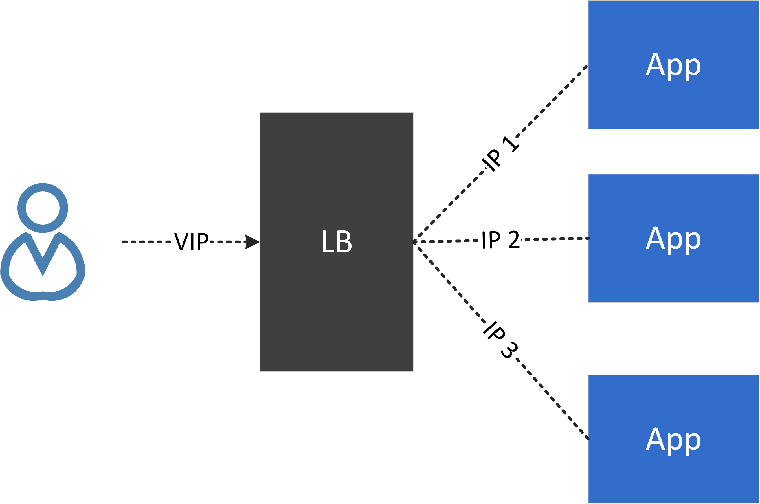
Fig. VIP and load balancing
1.4 Cross-host networking model#
How would an instance (container, VM, etc) on host A communicate with another instance on host B? Solution candidates:
Direct routing: BGP, etc
Tunneling: VxLAN, IPIP, GRE, etc
NAT: e.g. docker’s bridge network mode
2. Kubernetes node proxy model#
In Kubernetes, you can define an application to be a Service. A Service is an abstraction which defines a logical set of Pods and a policy by which to access them.
2.1 Service types#
There are 4 types of Services in K8S:
ClusterIP: access a
Servicevia a VIP, but this VIP could only be accessed within this cluster.NodePort: access a
ServiceviaNodeIP:NodePort, this means the port will be reserved on all nodes inside the cluster.ExternalIP: same as ClusterIP, but this VIP is accessible from outside of this cluster. externalIPs are provided by cloud vendors, thus are out of Kubernetes’s control (untrusted model).
LoadBalancer: works much the same as ExternalIP service, but the externalIPs are within Kubernetes’s control (trusted model).
This post will focus on ClusterIP, but other 3 types are much similar in the underlying implementation in terms of traffic interception and forwarding.
2.2 Service/proxy model#
An application can be declared as a Service.
A Service has a VIP (ClusterIP in this post) and multiple endpoints (backend pods).
Each pod can access an application directly by its VIP.
The node itself can access an application directly by its VIP.
To make this possible, a proxier is needed to run on each node. which is able to transparently intercept traffic destinated for any ClusterIP:Port [NOTE 1], then redistributes it to backend pods.
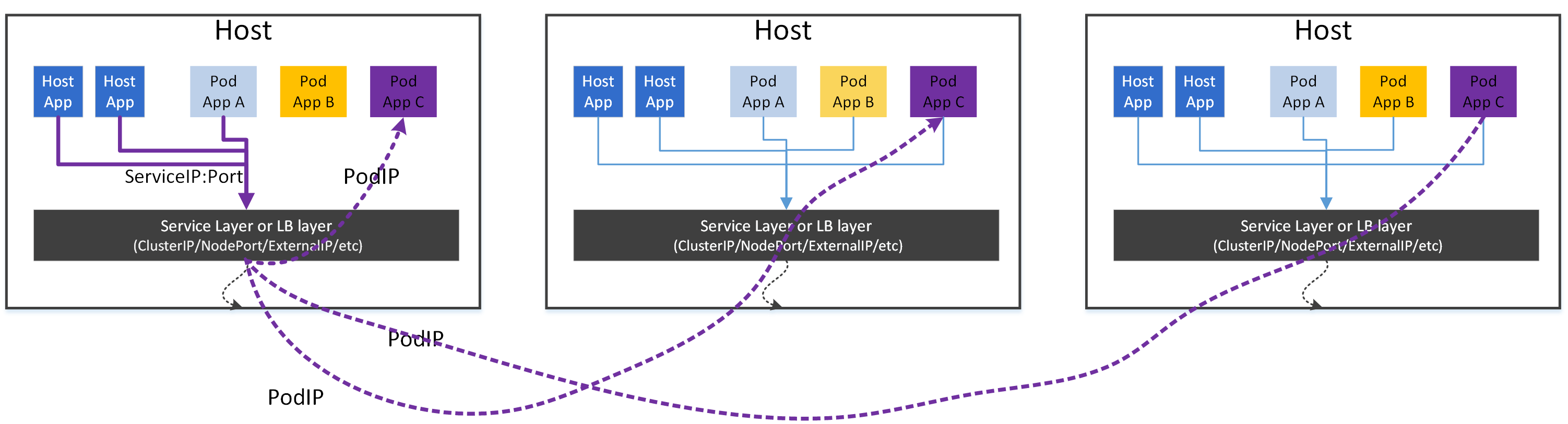
Fig. Kubernetes proxier model
NOTE 1
A common misunderstaning on ClusterIP is that ClusterIPs are ping-able - they are not by definition. If you ping a ClusterIP, most likely it will fail.
By definition, a
<Protocol,ClusterIP,Port>tuple uniquelly defines a Service (and thus an interception rule). For example, if a Service is defined as<tcp,10.7.0.100,80>, then the node proxy is only responsible for handling traffic oftcp:10.7.0.100:80, other traffics, eg.tcp:10.7.0.100:8080,udp:10.7.0.100:80are out of its duties. Thus the ClusterIP would not be reachable (ping traffic is ICMP).But if you are using kube-proxy with IPVS mode, the ClusterIP is indeed reachable via ping. This is because the IPVS mode implementation does more than what is asked. You will see the differences in the following sections.
2.3 Role of the node proxy: reverse proxy#
Think about the role of the node proxy: it actually acts as a reverse proxy in the K8S network model. That is, on each node, it will:
Hide all backend Pods to all clients
Filter all egress traffic (requests to backends)
For ingress traffic, it does nothing.
2.4 Performance issues#
Suppose we have an application on a host, and there are 1K Services in the K8S cluster, then we could never guess which Service the app is going to access in the next moment (ignore network policy here).
The result is: we have to make all Services be accessible to the app, and this requires us to apply all the proxy rules for all the Services in the cluster to the node. Expand this idea to the entire cluster, we conclude:
Proxy rules for all Services in the cluster should be applied to all nodes.
In some sense, this is a fully distributed proxy model, as any node has all the rules of all the Services in the cluster.
This leads to severe performance issues when the cluster grows large, as there can be hundreds of thousands of rules on each node [6,7].
3. Test environment#
3.1 Cluster topology and test environment#
We will use following environment for developing and testing our toy proxies:
A K8S cluster
one master node
one worker node
network solution: direct routing (PodIP directly routable)
A non-k8s-node, but it can reach the worker node and Pod (thanks to the direct routing networking scheme)
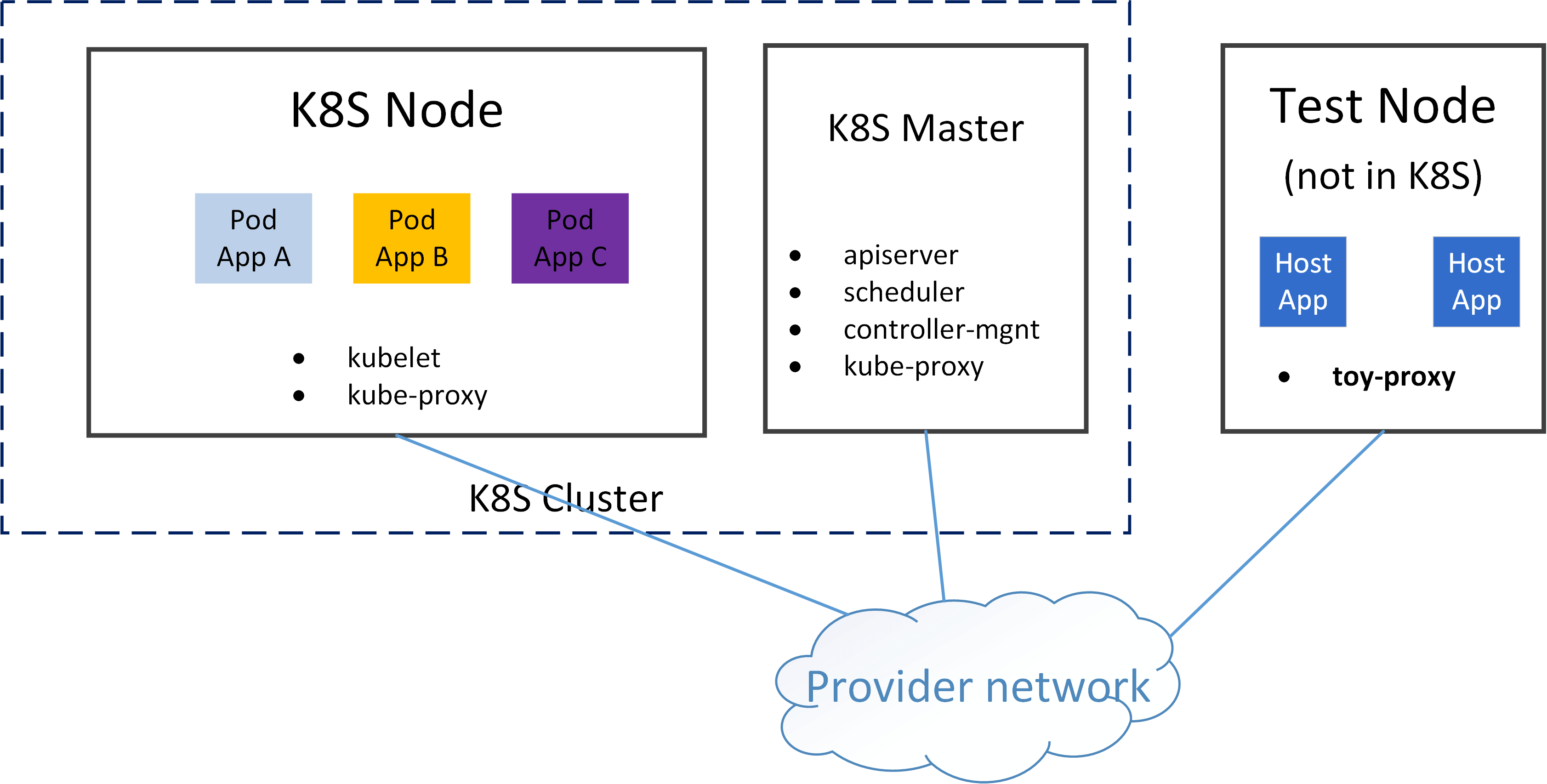
We will deploy Pods on the worker node, and access the applications in the Pods via ClusterIP from test node.
3.2 Create a Service#
Create a simple Statefulset, which includes a Service, and the Service will have one or more backend Pods:
# See appendix for webapp.yaml
$ kubectl create -f webapp.yaml

$ kubectl get svc -o wide webapp
NAME     TYPE        CLUSTER-IP     EXTERNAL-IP   PORT(S)   AGE     SELECTOR
webapp   ClusterIP   10.7.111.132   <none>        80/TCP    2m11s   app=webapp

$ kubectl get pod -o wide | grep webapp
webapp-0    2/2     Running   0    2m12s 10.5.41.204    node1    <none>  <none>
The application runs at port 80 with tcp protocol.
3.3 Reachability test#
First curl PodIP+Port:
$ curl 10.5.41.204:80
<!DOCTYPE html>
...
</html>
Successful! Then replace PodIP with ClusterIP and have another try:
$ curl 10.7.111.132:80
^C
As expected, it is unreachable!
In the next sections, we will investigate how to make the ClusterIP reachable with different means.
4. Implementation 1: proxy via userspace socket#
4.1 The middleman model#
The easiest realization of the node proxy model is: inserting our toy-proxy as a middleman in the traffic path on this host. For each connection from a local client to a ClusterIP:Port, we intercept the connection and split it into two separate connections:
connection 1: local client
<--->toy-proxyconnection 2:
toy-proxy<--->backend pods
The easiest way to achieve this is to implement it in userspace:
Listen to resources: start a daemon process, listen to K8S apiserver, watch Service (ClusterIP) and Endpoint (Pod) changes
Proxy traffic: for each connecting request from a local client to a Service (ClusterIP), intercepting the request by acting as a middleman
Dynamically apply proxy rules: for any Service/Endpoint updates, change
toy-proxyconnection settings accordingly
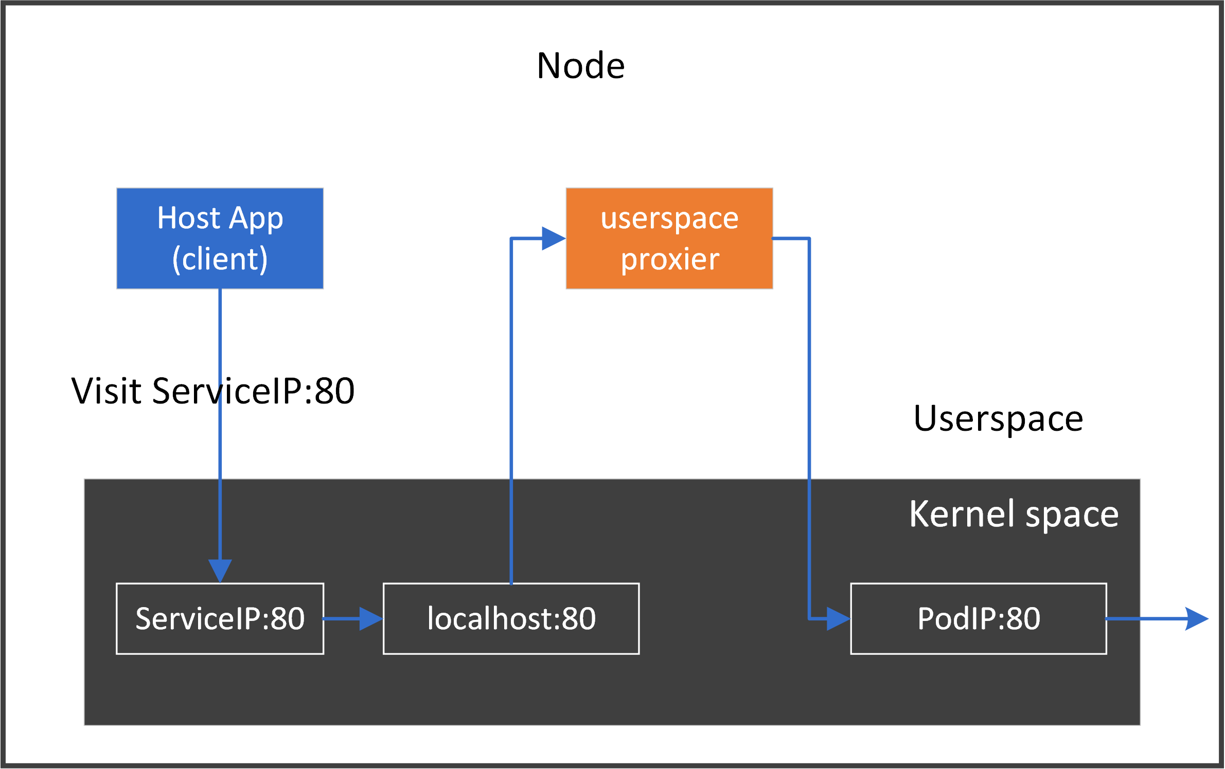
For our above test application webapp, following picture depicts the data flow:
4.2 Implementation#
Let’s see a proof-of-concept implementation for the above picture.
4.2.1 Code#
Omit error handling code for ease-of-reading:
func main() {
	clusterIP := "10.7.111.132"
	podIP := "10.5.41.204"
	port := 80
	proto := "tcp"

	addRedirectRules(clusterIP, port, proto)
	createProxy(podIP, port, proto)
}

func addRedirectRules(clusterIP string, port int, proto string) error {
	p := strconv.Itoa(port)
	cmd := exec.Command("iptables", "-t", "nat", "-A", "OUTPUT", "-p", "tcp",
		"-d", clusterIP, "--dport", p, "-j", "REDIRECT", "--to-port", p)
	return cmd.Run()
}

func createProxy(podIP string, port int, proto string) {
	host := ""
	listener, err := net.Listen(proto, net.JoinHostPort(host, strconv.Itoa(port)))

	for {
		inConn, err := listener.Accept()
		outConn, err := net.Dial(proto, net.JoinHostPort(podIP, strconv.Itoa(port)))

		go func(in, out *net.TCPConn) {
			var wg sync.WaitGroup
			wg.Add(2)
			fmt.Printf("Proxying %v <-> %v <-> %v <-> %v\n",
				in.RemoteAddr(), in.LocalAddr(), out.LocalAddr(), out.RemoteAddr())
			go copyBytes(in, out, &wg)
			go copyBytes(out, in, &wg)
			wg.Wait()
		}(inConn.(*net.TCPConn), outConn.(*net.TCPConn))
	}

	listener.Close()
}

func copyBytes(dst, src *net.TCPConn, wg *sync.WaitGroup) {
	defer wg.Done()
	if _, err := io.Copy(dst, src); err != nil {
		if !strings.HasSuffix(err.Error(), "use of closed network connection") {
			fmt.Printf("io.Copy error: %v", err)
		}
	}
	dst.Close()
	src.Close()
}
4.2.2 Some explanations#
1. Traffic interception#
We need to intercept all traffic destinated for ClusterIP:Port, but one question is: ClusterIP didn’t reside on on any network device of this node, which means we could not do something like listen(ClusterIP, Port).
Then, how could we perform the interception? The answer is: using the REDIRECT ability provided by iptables/netfilter.
The following command will direct all traffic that originally destinated for ClusterIP:Port to localhost:Port :
$ sudo iptables -t nat -A OUTPUT -p tcp -d $CLUSTER_IP --dport $PORT -j REDIRECT --to-port $PORT
Don’t be afraid if you can’t understanding this at present. We will cover this later.
Verify this by seeing the following output:
$ iptables -t nat -L -n
...
Chain OUTPUT (policy ACCEPT)
target     prot opt source      destination
REDIRECT   tcp  --  0.0.0.0/0   10.7.111.132         tcp dpt:80 redir ports 80
In our golang code, func addRedirectRules() wraps the above procedure.
2. Create proxy#
func createProxy() creates the userspace proxy, and maintains bi-directional forwarding.
4.3 Reachability test#
Build the code and run the binary:
$ go build toy-proxy-userspace.go
$ sudo ./toy-proxy-userspace
Now test accessing:
$ curl $CLUSTER_IP:$PORT
<!DOCTYPE html>
...
</html>
Successful! And our proxier’s message:
$ sudo ./toy-proxy-userspace
Creating proxy between <host ip>:53912 <-> 127.0.0.1:80 <-> <host ip>:40194 <-> 10.5.41.204:80
It says, for original connecting attempt of <host ip>:53912 <-> 10.7.111.132:80, we splitted it into two connections:
<host ip>:53912 <-> 127.0.0.1:80<host ip>:40194 <-> 10.5.41.204:80
4.3 Clean up#
Delete iptables rule:
$ iptables -t nat -L -n --line-numbers
...
Chain OUTPUT (policy ACCEPT)
num  target     prot opt source               destination
2    REDIRECT   tcp  --  0.0.0.0/0   10.7.111.132         tcp dpt:80 redir ports 80

# iptables -t nat -D OUTPUT <num>
$ iptables -t nat -D OUTPUT 2
or delete (flush) all rules if you get things messy:
$ iptables -t nat -F # delete all rules
$ iptables -t nat -X # delete all custom chains
4.4 Improvements#
In this toy implementation, we hijacked ClusterIP:80 to localhost:80, but
what if a native application on this host also wants to use
localhost:80? Further, what if multiple Services were exposing the same port number80?Apparently we need to distinguish these applications or Services. One way to fix this: for each proxy, allocate an unused temporary port
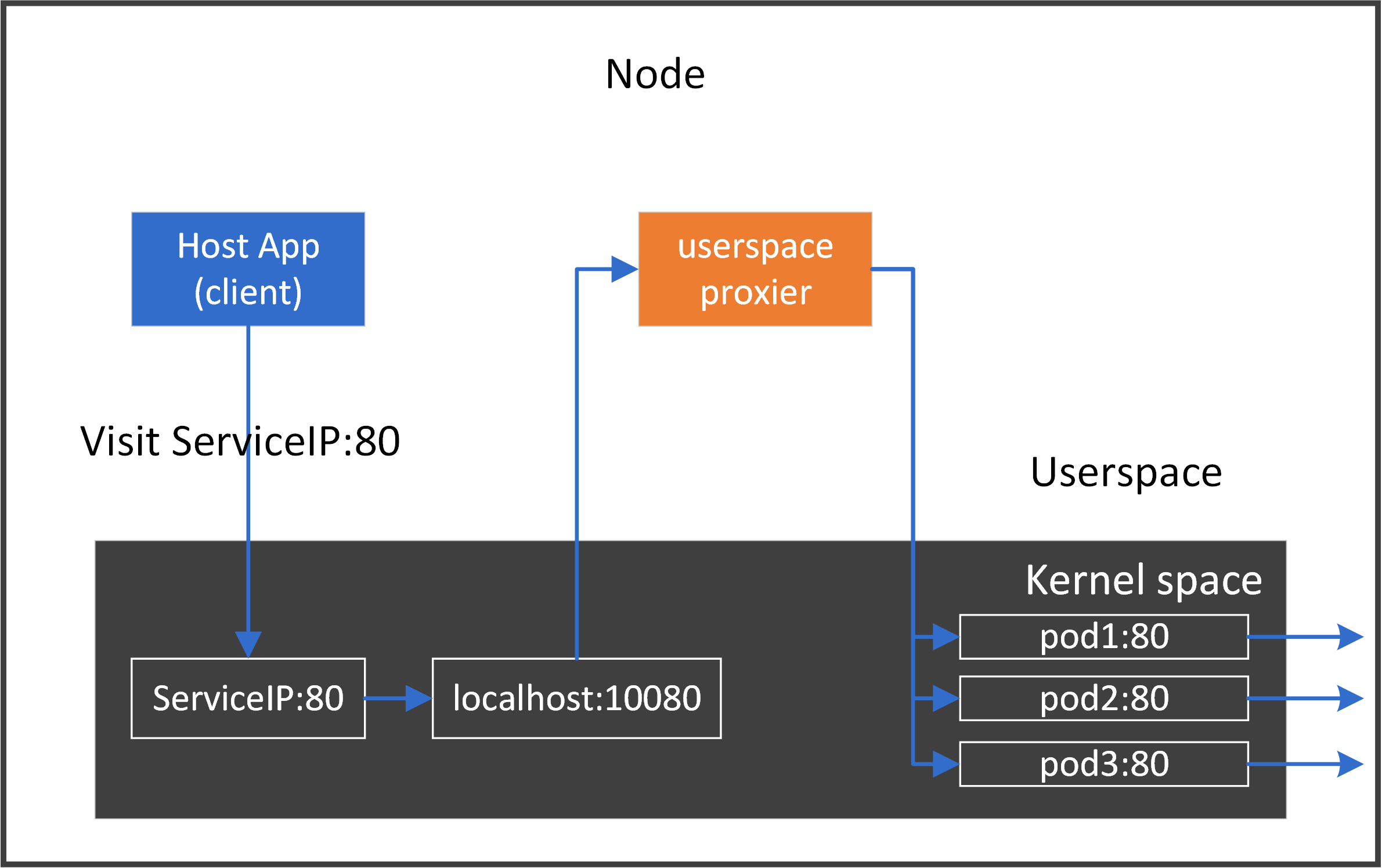
TmpPort, hijackClusterIP:Porttolocalhost:TmpPort, e.g. app1 using10001, app2 using10002.The above code only handles one backend, what if there were multiple backend pods?
We need to distribute connections to different backend pods by load balancing algorithms.
Combining 1 & 2, the more general proxy should work like the following:
4.5 Pros and Cons#
This method is fairly easy for understanding and implementation, but it would definitly suffer from bad performance, as it has to copy bytes between the two side, as well as between kernel and userspace.
We won’t spend much time on this, see the vanilla implementation of userspace kube-proxy if you are interested.
5. Implementation 2: proxy via iptables#
Let’s see another way to do the proxy task.
The main bottleneck of userspace proxier comes from the kernel-userspace switching and data copying. If we can implement a proxy entirely in kernel space, it will beat the userspace one greatly. iptables can be used to achieve this goal.
Before we start, let’s first figure out the traffic path when we do curl ClusterIP:Port, then we will investigate how to make it reachable with iptables rules.
5.1 Host -> ClusterIP (single backend)#
As ClusterIP doesn’t reside on any network device, in order to let our packets finally reach the backend Pods, we need to convert the ClusterIP to PodIP (routable), namely:
Condition: if packets has
dst=ClusterIP,proto=tcp,dport=80Action: replace
dst=ClusterIPwithdst=PodIPin IP header of the packets
In network terminology, this is a network address translation (NAT) process.
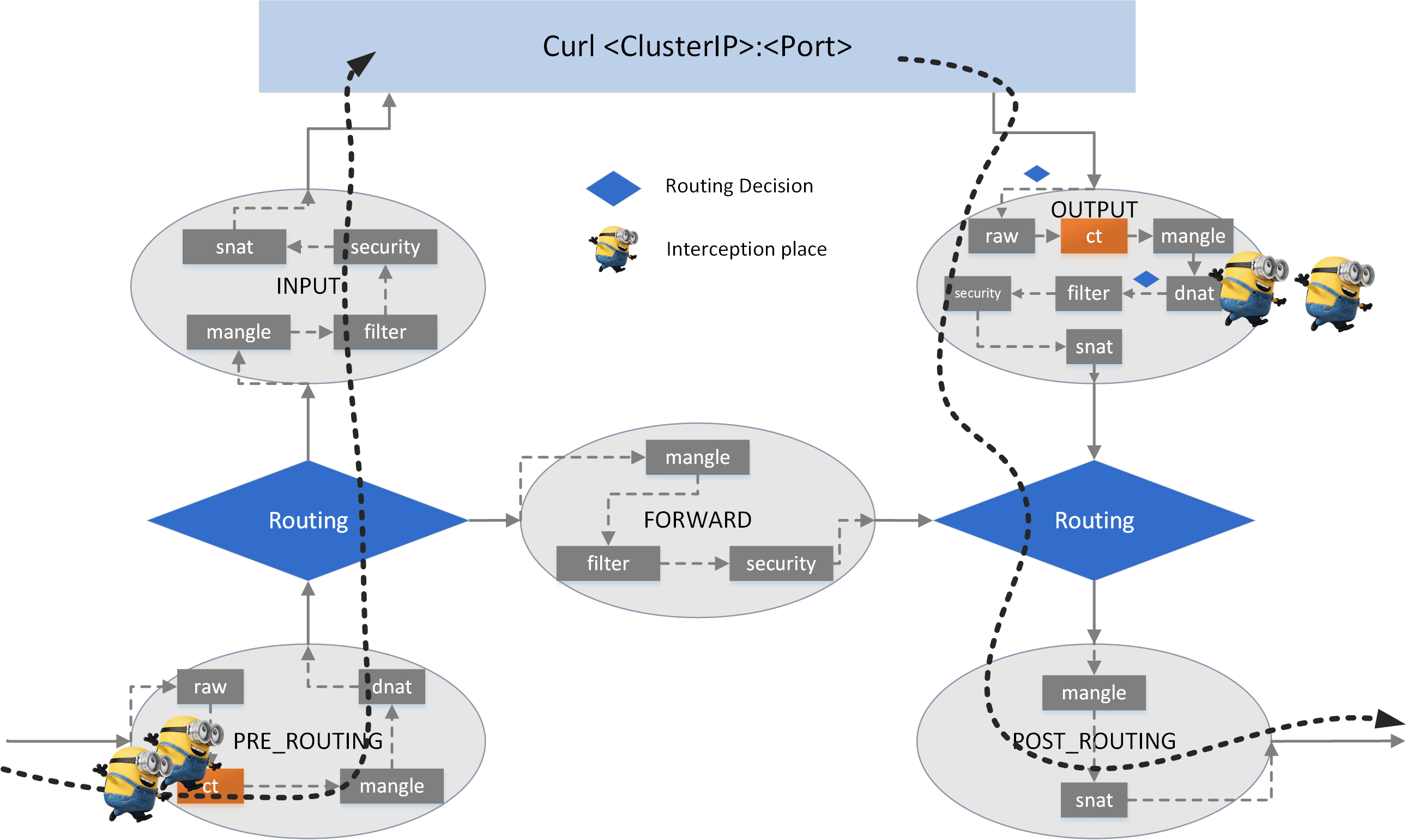
5.1.1 Where to perform the DNAT#
Look at the egress path of our curl process:
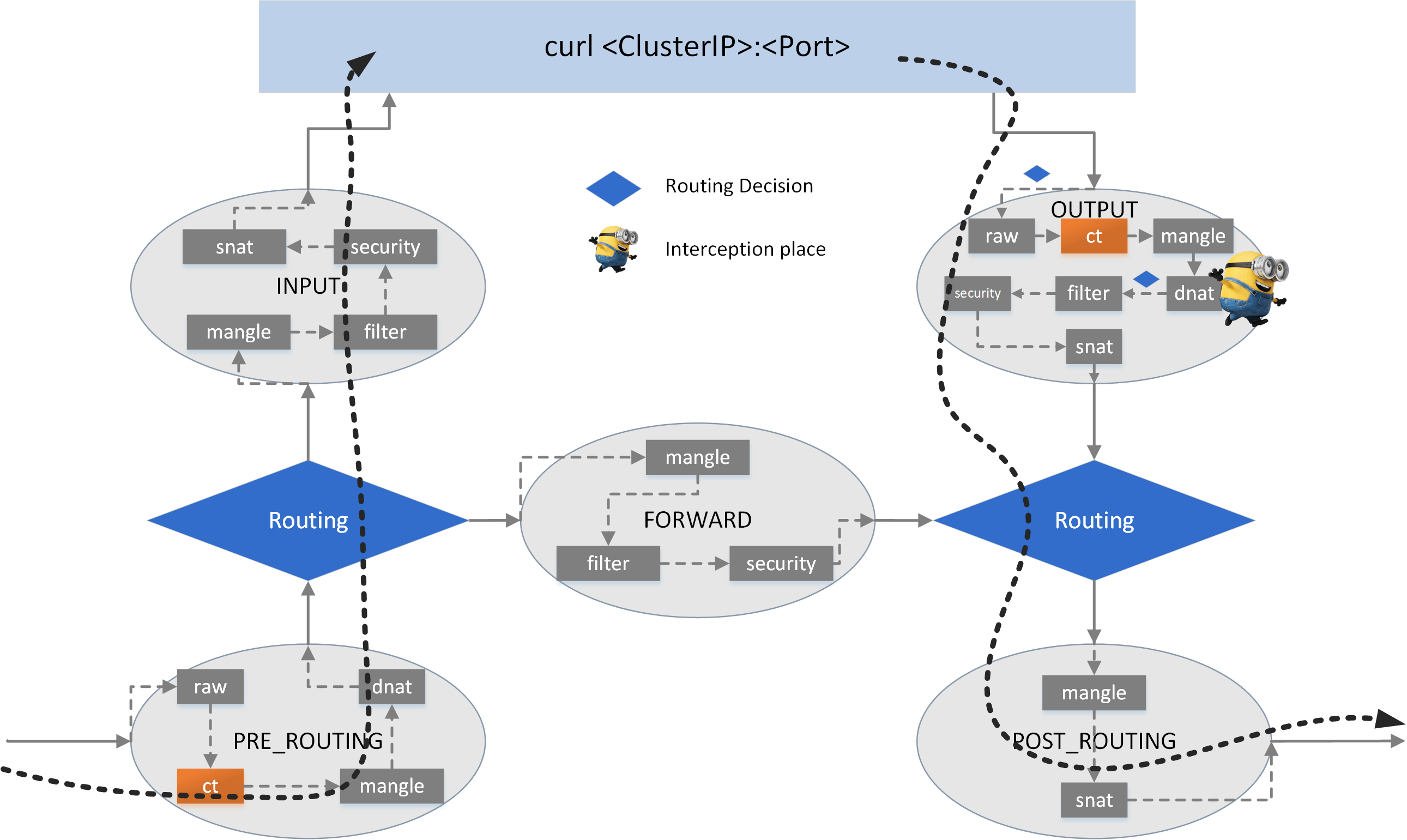
curl -> raw -> CT -> mangle -> dnat -> filter -> security -> snat -> ROUTING -> mangle -> snat -> NIC
there is only one dnat (chain) - which is in the OUTPUT hook - where we could do DNAT.
Let’s see how to realize it.
5.1.2 Check current NAT rules#
NAT rules are organized into nat table. Check the current rules in nat table:
# -t <table>
# -L list rules
# -n numeric output
$ iptables -t nat -L -n
Chain PREROUTING (policy ACCEPT)

Chain INPUT (policy ACCEPT)

Chain OUTPUT (policy ACCEPT)
DOCKER     all  --  0.0.0.0/0    !127.0.0.0/8   ADDRTYPE match dst-type LOCAL

Chain POSTROUTING (policy ACCEPT)
The output shows that there are no rules except DOCKER related ones. Those DOCKER rules are inserted by docker upon installation, but they won’t affect our experiments in this post. So we just ignore them.
5.1.3 Add DNAT rules#
For ease-of-viewing, we no longer wrap shell commands with go code, but directly present the commands themselves in the next.
NOTE: Before proceed on, make sure you have deleted all the rules that added in the previous section.
Confirm that the ClusterIP is not reachable at present:
$ curl $CLUSTER_IP:$PORT
^C
Now add our egress NAT rule:
$ cat ENV
CLUSTER_IP=10.7.111.132
POD_IP=10.5.41.204
PORT=80
PROTO=tcp

# -p               <protocol>
# -A               add rule
# --dport          <dst port>
# -d               <dst ip>
# -j               jump to
# --to-destination <ip>:<port>
$ iptables -t nat -A OUTPUT -p $PROTO --dport $PORT -d $CLUSTER_IP -j DNAT --to-destination $POD_IP:$PORT
Check the table again:
$ iptables -t nat -L -n

Chain OUTPUT (policy ACCEPT)
target     prot opt source      destination
DNAT       tcp  --  0.0.0.0/0   10.7.111.132   tcp dpt:80 to:10.5.41.204:80
As can be seen, the rule is added.
5.1.4 Test reachability#
Now curl again:
$ curl $CLUSTER_IP:$PORT
<!DOCTYPE html>
...
</html>
That’s it, DNAT successful!
But wait! The fact that egress traffic be NATed meets our expectation, but we haven’t added any rules in the reverse (namely, ingress) path, how could the traffic be OK on both directions? It turns out that when you add a NAT rule for one direction, kernel would automatically add the reserve rules on the other direction! This works collaboratively with the conntrack (CT, connection tracking) module.
5.1.5 Cleanup#
Delete this rule:
$ iptables -t nat -L -n --line-numbers
...
Chain OUTPUT (policy ACCEPT)
num  target     prot opt source               destination
2    DNAT       tcp  --  0.0.0.0/0   10.7.111.132   tcp dpt:80 to:10.5.41.204:80

# iptables -t <table> -D <chain> <num>
$ iptables -t nat -D OUTPUT 2
5.2 Host -> ClusterIP (multiple backends)#
Now let’s see the multiple-backend case.
NOTE: Before proceed on, make sure you have deleted all the rules you added in previous section.
5.2.1 Scale up webapp#
First scale up our Service to 2 backend pods:
$ kubectl scale sts webapp --replicas=2
statefulset.apps/webapp scaled
statefulset.apps/webapp scaled

$ kubectl get pod -o wide | grep webapp
webapp-0   2/2     Running   0   1h24m   10.5.41.204    node1    <none> <none>
webapp-1   2/2     Running   0   11s     10.5.41.5      node1    <none> <none>
5.2.2 Add DNAT rules with load balancing#
We use the statistic module in iptables to distribute requests to backend Pods with probability, in this way we would achieve the load balancing effect:
# -m <module>
$ iptables -t nat -A OUTPUT -p $PROTO --dport $PORT -d $CLUSTER_IP \
    -m statistic --mode random --probability 0.5  \
    -j DNAT --to-destination $POD1_IP:$PORT
$ iptables -t nat -A OUTPUT -p $PROTO --dport $PORT -d $CLUSTER_IP \
    -m statistic --mode random --probability 1.0  \
    -j DNAT --to-destination $POD2_IP:$PORT
The above commands distribute requests among two Pods randomly, each with 50% probability.
Now check the rules:
$ iptables -t nat -L -n
...
Chain OUTPUT (policy ACCEPT)
target  prot opt source      destination
DNAT    tcp  --  0.0.0.0/0   10.7.111.132  tcp dpt:80 statistic mode random probability 0.50000000000 to:10.5.41.204:80
DNAT    tcp  --  0.0.0.0/0   10.7.111.132  tcp dpt:80 statistic mode random probability 1.00000000000 to:10.5.41.5:80
5.2.3 Verify load balancing#
Now let’s ensure the load balancing actually works. We make 8 requests, and capture the real PodIPs this host communicates with.
Open a shell on test node:
$ for i in {1..8}; do curl $CLUSTER_IP:$PORT 2>&1 >/dev/null; sleep 1; done
another shell window on test node:
$ tcpdump -nn -i eth0 port $PORT | grep "GET /"
10.21.0.7.48306 > 10.5.41.5.80:   ... HTTP: GET / HTTP/1.1
10.21.0.7.48308 > 10.5.41.204.80: ... HTTP: GET / HTTP/1.1
10.21.0.7.48310 > 10.5.41.204.80: ... HTTP: GET / HTTP/1.1
10.21.0.7.48312 > 10.5.41.5.80:   ... HTTP: GET / HTTP/1.1
10.21.0.7.48314 > 10.5.41.5.80:   ... HTTP: GET / HTTP/1.1
10.21.0.7.48316 > 10.5.41.204.80: ... HTTP: GET / HTTP/1.1
10.21.0.7.48318 > 10.5.41.5.80:   ... HTTP: GET / HTTP/1.1
10.21.0.7.48320 > 10.5.41.204.80: ... HTTP: GET / HTTP/1.1
4 times with Pod1 and 4 times with Pod2, 50% with each pod, exactly what’s expected.
5.2.4 Cleanup#
$ iptables -t nat -L -n --line-numbers
...
Chain OUTPUT (policy ACCEPT)
num  target     prot opt source               destination
2    DNAT    tcp  --  0.0.0.0/0   10.7.111.132  tcp dpt:80 statistic mode random probability 0.50000000000 to:10.5.41.204:80
3    DNAT    tcp  --  0.0.0.0/0   10.7.111.132  tcp dpt:80 statistic mode random probability 1.00000000000 to:10.5.41.5:80

$ iptables -t nat -D OUTPUT 2
$ iptables -t nat -D OUTPUT 3
5.3 Pod (app A) -> ClusterIP (app B)#
What should we do in the following case: appA in podA@hostA would like to clusterIpB, where clusterIpB’s backend pod is podB, and the latter resides on hostB?
Actually this is much the same as Host --> ClusterIP case, but with one more thing: after DNAT is performed, the source node (hostA) must send the packet to the destination node (hostB) on which the destination Pod resides. Depending on the cross-host networking choices, this varies a lot, that’s why so many networking solutions take place:
Direct routing: the host just needs to send the packets out, as the PodIP is routable. Solutions include:
Calico + bird
Cilium + kube-router (Cilium’s default solution for BGP)
Cilium + bird (actually this is just our test env networking solutions here)
Tunneling: must place an agent on each host, which performs encap after DNAT, and decap before SNAT. Solutions include:
Calico + VxLAN mode
Flannel + IPIP mode
Flannel + VxLAN mode
Cilium + VxLAN mode
AWS-like ENI mode: similar as direct routing, but BGP agent is not needed.
Cilium + ENI mode
Below shows the tunneling case:
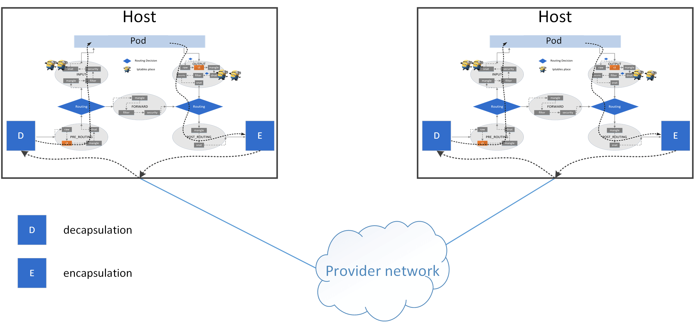
The tunneling related responsibilities of the agent including:
Sync tunnel information between all nodes, e.g. info describing which instance is on which node.
Perform encapsulation after DNAT for pod traffic: for all egress traffic, e.g. from
hostAwithdst=PodIP, wherePodIPis onhostB, encapsulate packets by add another header, e.g. VxLAN header, where the encapsulation header hassrc=hostA_IP,dst=hostB_IP.Perform decapsulation before SNAT for pod traffic: decapsulate each ingress encasulated packet: remove outer layer (e.g. VxLAN header).
Also, the host needs to decide:
Which packets should go to decapsulator (pod traffic), which shouldn’t (e.g. host traffic)
Which packets should go to encapsulator (pod traffic), which shouldn’t (e.g. host traffic)
5.4 Re-structure the iptables rules#
NOTE: Before proceed on, make sure you have deleted all the rules you added in previous section.
When you have plentiful Services, the iptables rules on each node will be fairly complicated, thus you need some structural work to organize those rules.
In this section, we will create several dedicated iptables chains in nat table, specifically:
chain
KUBE-SERVICES: intercept all egress traffic inOUTPUTchain ofnattable to this chain, do DNAT if they are destinated for a ClusterIPchain
KUBE-SVC-WEBAPP: intercept all traffic inKUBE-SERVICESto this chain ifdst,protoandportmatchchain
KUBE-SEP-WEBAPP1: intercept 50% of the traffic inKUBE-SVC-WEBAPPto herechain
KUBE-SEP-WEBAPP2: intercept 50% of the traffic inKUBE-SVC-WEBAPPto here
The DNAT path now will be:
OUTPUT -> KUBE-SERVICES -> KUBE-SVC-WEBAPP --> KUBE-SEP-WEBAPP1
                                         \
                                          \--> KUBE-SEP-WEBAPP2
If you have multiple services, the DNAT path would be like:
OUTPUT -> KUBE-SERVICES -> KUBE-SVC-A --> KUBE-SEP-A1
                      |              \--> KUBE-SEP-A2
                      |
                      |--> KUBE-SVC-B --> KUBE-SEP-B1
                      |              \--> KUBE-SEP-B2
                      |
                      |--> KUBE-SVC-C --> KUBE-SEP-C1
                                     \--> KUBE-SEP-C2
iptables commands:
$ cat add-dnat-structured.sh
source ../ENV

set -x

KUBE_SVCS="KUBE-SERVICES"        # chain that serves as kubernetes service portal
SVC_WEBAPP="KUBE-SVC-WEBAPP"     # chain that serves as DNAT entrypoint for webapp
WEBAPP_EP1="KUBE-SEP-WEBAPP1"    # chain that performs dnat to pod1
WEBAPP_EP2="KUBE-SEP-WEBAPP2"    # chain that performs dnat to pod2

# OUTPUT -> KUBE-SERVICES
sudo iptables -t nat -N $KUBE_SVCS
sudo iptables -t nat -A OUTPUT -p all -s 0.0.0.0/0 -d 0.0.0.0/0 -j $KUBE_SVCS

# KUBE-SERVICES -> KUBE-SVC-WEBAPP
sudo iptables -t nat -N $SVC_WEBAPP
sudo iptables -t nat -A $KUBE_SVCS -p $PROTO -s 0.0.0.0/0 -d $CLUSTER_IP --dport $PORT -j $SVC_WEBAPP

# KUBE-SVC-WEBAPP -> KUBE-SEP-WEBAPP*
sudo iptables -t nat -N $WEBAPP_EP1
sudo iptables -t nat -N $WEBAPP_EP2
sudo iptables -t nat -A $WEBAPP_EP1 -p $PROTO -s 0.0.0.0/0 -d 0.0.0.0/0 --dport $PORT -j DNAT --to-destination $POD1_IP:$PORT
sudo iptables -t nat -A $WEBAPP_EP2 -p $PROTO -s 0.0.0.0/0 -d 0.0.0.0/0 --dport $PORT -j DNAT --to-destination $POD2_IP:$PORT
sudo iptables -t nat -A $SVC_WEBAPP -p $PROTO -s 0.0.0.0/0 -d 0.0.0.0/0 -m statistic --mode random --probability 0.5  -j $WEBAPP_EP1
sudo iptables -t nat -A $SVC_WEBAPP -p $PROTO -s 0.0.0.0/0 -d 0.0.0.0/0 -m statistic --mode random --probability 1.0  -j $WEBAPP_EP2
Now test our design:
$ ./add-dnat-structured.sh
++ KUBE_SVCS=KUBE-SERVICES
++ SVC_WEBAPP=KUBE-SVC-WEBAPP
++ WEBAPP_EP1=KUBE-SEP-WEBAPP1
++ WEBAPP_EP2=KUBE-SEP-WEBAPP2
++ sudo iptables -t nat -N KUBE-SERVICES
++ sudo iptables -t nat -A OUTPUT -p all -s 0.0.0.0/0 -d 0.0.0.0/0 -j KUBE-SERVICES
++ sudo iptables -t nat -N KUBE-SVC-WEBAPP
++ sudo iptables -t nat -A KUBE-SERVICES -p tcp -s 0.0.0.0/0 -d 10.7.111.132 --dport 80 -j KUBE-SVC-WEBAPP
++ sudo iptables -t nat -N KUBE-SEP-WEBAPP1
++ sudo iptables -t nat -N KUBE-SEP-WEBAPP2
++ sudo iptables -t nat -A KUBE-SEP-WEBAPP1 -p tcp -s 0.0.0.0/0 -d 0.0.0.0/0 --dport 80 -j DNAT --to-destination 10.5.41.204:80
++ sudo iptables -t nat -A KUBE-SEP-WEBAPP2 -p tcp -s 0.0.0.0/0 -d 0.0.0.0/0 --dport 80 -j DNAT --to-destination 10.5.41.5:80
++ sudo iptables -t nat -A KUBE-SVC-WEBAPP -p tcp -s 0.0.0.0/0 -d 0.0.0.0/0 -m statistic --mode random --probability 0.5 -j KUBE-SEP-WEBAPP1
++ sudo iptables -t nat -A KUBE-SVC-WEBAPP -p tcp -s 0.0.0.0/0 -d 0.0.0.0/0 -m statistic --mode random --probability 1.0 -j KUBE-SEP-WEBAPP2
Check the rules:
$ sudo iptables -t nat -L -n
...
Chain OUTPUT (policy ACCEPT)
target     prot opt source               destination
KUBE-SERVICES  all  --  0.0.0.0/0            0.0.0.0/0

Chain KUBE-SEP-WEBAPP1 (1 references)
target     prot opt source               destination
DNAT       tcp  --  0.0.0.0/0            0.0.0.0/0            tcp dpt:80 to:10.5.41.204:80

Chain KUBE-SEP-WEBAPP2 (1 references)
target     prot opt source               destination
DNAT       tcp  --  0.0.0.0/0            0.0.0.0/0            tcp dpt:80 to:10.5.41.5:80

Chain KUBE-SERVICES (1 references)
target     prot opt source               destination
KUBE-SVC-WEBAPP  tcp  --  0.0.0.0/0            10.7.111.132         tcp dpt:80

Chain KUBE-SVC-WEBAPP (1 references)
target     prot opt source               destination
KUBE-SEP-WEBAPP1  tcp  --  0.0.0.0/0            0.0.0.0/0            statistic mode random probability 0.50000000000
KUBE-SEP-WEBAPP2  tcp  --  0.0.0.0/0            0.0.0.0/0            statistic mode random probability 1.00000000000
$ curl $CLUSTER_IP:$PORT
<!DOCTYPE html>
...
</html>
Successful!
If comparing the above output with vanilla kube-proxy ones, you’ll find that they are much the same. For example, below is taken from a kube-proxy enabled node:
Chain OUTPUT (policy ACCEPT)
target         prot opt source               destination
KUBE-SERVICES  all  --  0.0.0.0/0            0.0.0.0/0            /* kubernetes service portals */

Chain KUBE-SERVICES (2 references)
target                     prot opt source               destination
KUBE-SVC-YK2SNH4V42VSDWIJ  tcp  --  0.0.0.0/0            10.7.22.18           /* default/nginx:web cluster IP */ tcp dpt:80

Chain KUBE-SVC-YK2SNH4V42VSDWIJ (1 references)
target                     prot opt source               destination
KUBE-SEP-GL2BLSI2B4ICU6WH  all  --  0.0.0.0/0            0.0.0.0/0            /* default/nginx:web */ statistic mode random probability 0.33332999982
KUBE-SEP-AIRRSG3CIF42U3PX  all  --  0.0.0.0/0            0.0.0.0/0            /* default/nginx:web */

Chain KUBE-SEP-GL2BLSI2B4ICU6WH (1 references)
target          prot opt source               destination
DNAT            tcp  --  0.0.0.0/0            0.0.0.0/0            /* default/nginx:web */ tcp to:10.244.3.181:80

Chain KUBE-SEP-AIRRSG3CIF42U3PX (1 references)
target          prot opt source               destination
DNAT            tcp  --  0.0.0.0/0            0.0.0.0/0            /* default/nginx:web */ tcp to:10.244.3.182:80
5.5 Further Re-structure the iptables rules#
TODO: add rules for traffic coming from outside of cluster.
6. Implementation 3: proxy via IPVS#
Although iptables-based proxy beats userspace-based one with great performance gain, it still suffers from severe performance degrades when the cluster has too much Services [6,7].
Essentially this is because iptables verdicts are chain-based, it is a linear algorithm with O(n) complexity. A good alternative to iptables is IPVS - an in-kernel L4 load balancer, which uses ipset in the underlying (hash implementation), thus has a complexity of O(1).
Let’s see how to achieve the same goal with IPVS.
NOTE: Before proceed on, make sure you have deleted all the rules you added in previous section.
6.1 Install IPVS#
$ yum install -y ipvsadm

# -l  list load balancing status
# -n  numeric output
$ ipvsadm -ln
Prot LocalAddress:Port Scheduler Flags
  -> RemoteAddress:Port           Forward Weight ActiveConn InActConn
No rules by default.
6.2 Add virtual/real servers#
Achieve load balancing with IPVS:
# -A/--add-service           add service
# -t/--tcp-service <address> VIP + Port
# -s <method>                scheduling-method
# -r/--real-server <address> real backend IP + Port
# -m                         masquerading (NAT)
$ ipvsadm -A -t $CLUSTER_IP:$PORT -s rr
$ ipvsadm -a -t $CLUSTER_IP:$PORT -r $POD1_IP -m
$ ipvsadm -a -t $CLUSTER_IP:$PORT -r $POD2_IP -m
or use my script:
$ ./ipvs-add-server.sh
Adding virtual server CLUSTER_IP:PORT=10.7.111.132:80 ...
Adding real servers ...
10.7.111.132:80 -> 10.5.41.204
10.7.111.132:80 -> 10.5.41.5
Done
Check status again:
$ ipvsadm -ln
Prot LocalAddress:Port Scheduler Flags
  -> RemoteAddress:Port           Forward Weight ActiveConn InActConn
TCP  10.7.111.132:80 rr
  -> 10.5.41.5:80                 Masq    1      0          0
  -> 10.5.41.204:80               Masq    1      0          0
Some explanations:
For all traffic destinated for
10.7.111.132:80, load-balancing it to10.5.41.5:80and10.5.41.204:80.Use round-robin (rr) algorithm for load balancing.
Two backends each with weight
1(50% of each).Use MASQ (enhanced SNAT) for traffic forwarding between VIP and RealIPs.
6.3 Verify#
$ for i in {1..8}; do curl $CLUSTER_IP:$PORT 2>&1 >/dev/null; sleep 1; done
$ tcpdump -nn -i eth0 port $PORT | grep "HTTP: GET"
IP 10.21.0.7.49556 > 10.5.41.204.80: ... HTTP: GET / HTTP/1.1
IP 10.21.0.7.49558 > 10.5.41.5.80  : ... HTTP: GET / HTTP/1.1
IP 10.21.0.7.49560 > 10.5.41.204.80: ... HTTP: GET / HTTP/1.1
IP 10.21.0.7.49562 > 10.5.41.5.80  : ... HTTP: GET / HTTP/1.1
IP 10.21.0.7.49566 > 10.5.41.204.80: ... HTTP: GET / HTTP/1.1
IP 10.21.0.7.49568 > 10.5.41.5.80  : ... HTTP: GET / HTTP/1.1
IP 10.21.0.7.49570 > 10.5.41.204.80: ... HTTP: GET / HTTP/1.1
IP 10.21.0.7.49572 > 10.5.41.5.80  : ... HTTP: GET / HTTP/1.1
Perfect!
6.4 Clean up#
$ ./ipvs-del-server.sh
Deleting real servers ...
10.7.111.132:80 -> 10.5.41.204
10.7.111.132:80 -> 10.5.41.5
Deleting virtual server CLUSTER_IP:PORT=10.7.111.132:80 ...
Done
7. Implementation 4: proxy via tc-level ebpf#
This is also an O(1) proxy, but has even higher performance compared with IPVS.
Let’s see how to implement the proxy function with eBPF in less than 100 lines of C code.
7.1 Prerequisites#
If you have enough time and interests to eBPF/BPF, consider reading through Cilium: BPF and XDP Reference Guide, it’s a perfect documentation for developers.
7.2 Implementation#
For the egress part, basic idea:
For all traffic, if
dst=CLUSTER_IP && proto==TCP && dport==80,Change destination IP:
CLUSTER_IP -> POD_IP.Update checksum filelds in IP and TCP headers (otherwise the packets will be dropped).
__section("egress")
int tc_egress(struct __sk_buff *skb)
{
    const __be32 cluster_ip = 0x846F070A; // 10.7.111.132
    const __be32 pod_ip = 0x0529050A;     // 10.5.41.5

    const int l3_off = ETH_HLEN;    // IP header offset
    const int l4_off = l3_off + 20; // TCP header offset: l3_off + sizeof(struct iphdr)
    __be32 sum;                     // IP checksum

    void *data = (void *)(long)skb->data;
    void *data_end = (void *)(long)skb->data_end;
    if (data_end < data + l4_off) { // not our packet
        return TC_ACT_OK;
    }

    struct iphdr *ip4 = (struct iphdr *)(data + l3_off);
    if (ip4->daddr != cluster_ip || ip4->protocol != IPPROTO_TCP /* || tcp->dport == 80 */) {
        return TC_ACT_OK;
    }

    // DNAT: cluster_ip -> pod_ip, then update L3 and L4 checksum
    sum = csum_diff((void *)&ip4->daddr, 4, (void *)&pod_ip, 4, 0);
    skb_store_bytes(skb, l3_off + offsetof(struct iphdr, daddr), (void *)&pod_ip, 4, 0);
    l3_csum_replace(skb, l3_off + offsetof(struct iphdr, check), 0, sum, 0);
	l4_csum_replace(skb, l4_off + offsetof(struct tcphdr, check), 0, sum, BPF_F_PSEUDO_HDR);

    return TC_ACT_OK;
}
and the ingress part, quite similar to the egress one:
__section("ingress")
int tc_ingress(struct __sk_buff *skb)
{
    const __be32 cluster_ip = 0x846F070A; // 10.7.111.132
    const __be32 pod_ip = 0x0529050A;     // 10.5.41.5

    const int l3_off = ETH_HLEN;    // IP header offset
    const int l4_off = l3_off + 20; // TCP header offset: l3_off + sizeof(struct iphdr)
    __be32 sum;                     // IP checksum

    void *data = (void *)(long)skb->data;
    void *data_end = (void *)(long)skb->data_end;
    if (data_end < data + l4_off) { // not our packet
        return TC_ACT_OK;
    }

    struct iphdr *ip4 = (struct iphdr *)(data + l3_off);
    if (ip4->saddr != pod_ip || ip4->protocol != IPPROTO_TCP /* || tcp->dport == 80 */) {
        return TC_ACT_OK;
    }

    // SNAT: pod_ip -> cluster_ip, then update L3 and L4 header
    sum = csum_diff((void *)&ip4->saddr, 4, (void *)&cluster_ip, 4, 0);
    skb_store_bytes(skb, l3_off + offsetof(struct iphdr, saddr), (void *)&cluster_ip, 4, 0);
    l3_csum_replace(skb, l3_off + offsetof(struct iphdr, check), 0, sum, 0);
	l4_csum_replace(skb, l4_off + offsetof(struct tcphdr, check), 0, sum, BPF_F_PSEUDO_HDR);

    return TC_ACT_OK;
}

char __license[] __section("license") = "GPL";
7.3 Compile and load into kernel#
Now use my tiny script for compiling and loading into kernel:
$ ./compile-and-load.sh
...
++ sudo tc filter show dev eth0 egress
filter protocol all pref 49152 bpf chain 0
filter protocol all pref 49152 bpf chain 0 handle 0x1 toy-proxy-bpf.o:[egress] direct-action not_in_hw id 18 tag f5f39a21730006aa jited

++ sudo tc filter show dev eth0 ingress
filter protocol all pref 49152 bpf chain 0
filter protocol all pref 49152 bpf chain 0 handle 0x1 toy-proxy-bpf.o:[ingress] direct-action not_in_hw id 19 tag b41159c5873bcbc9 jited
where the script looks like:
$ cat compile-and-load.sh
set -x

NIC=eth0

# compile c code into bpf code
clang -O2 -Wall -c toy-proxy-bpf.c -target bpf -o toy-proxy-bpf.o

# add tc queuing discipline (egress and ingress buffer)
sudo tc qdisc del dev $NIC clsact 2>&1 >/dev/null
sudo tc qdisc add dev $NIC clsact

# load bpf code into the tc egress and ingress hook respectively
sudo tc filter add dev $NIC egress bpf da obj toy-proxy-bpf.o sec egress
sudo tc filter add dev $NIC ingress bpf da obj toy-proxy-bpf.o sec ingress

# show info
sudo tc filter show dev $NIC egress
sudo tc filter show dev $NIC ingress
7.4 Verify#
$ curl $CLUSTER_IP:$PORT
<!DOCTYPE html>
...
</html>
Perfect!
7.5 Cleanup#
$ sudo tc qdisc del dev $NIC clsact 2>&1 >/dev/null
7.6 Explanations#
TODO.
See some of my previous posts for bpf/cilium.
7.7 Improvements#
And one problem of our tc-ebpf based proxy: this is packet-level NAT scheme, which means, we have to perform NAT on every single packet.
Can we do it better? Of course!
8. Implementation 5: proxy via socket-level ebpf#
8.1 Hook earlier#
eBPF code can be attached at different places (levels) in the kernel:
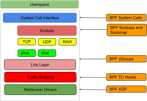
Image from here
By hooking connections at socket-level, the packet-level NAT would be bypassed: for each connection, we just need to perform NAT once! (for TCP).
What’s more, such a functionality can be implemented in less than 30 lines of C (ebpf) code.
8.2 Implementation#
static int
__sock4_xlate_fwd(struct bpf_sock_addr *ctx)
{
    const __be32 cluster_ip = 0x846F070A; // 10.7.111.132
    const __be32 pod_ip = 0x0529050A;     // 10.5.41.5

    if (ctx->user_ip4 != cluster_ip) {
        return 0;
    }

    ctx->user_ip4 = pod_ip;
    return 0;
}

__section("connect4")
int sock4_connect(struct bpf_sock_addr *ctx)
{
    __sock4_xlate_fwd(ctx);
    return SYS_PROCEED;
}
connect4 indicates that this piece of code will be triggered when there are IPv4 socket connection events (connect() system call). And when it happens, the code will modify the socket metadata, replacing destination IP (ClusterIP) with PodIP then return (continue connecting process, but with new destination IP).
This hooking operates so early (socket-level, above TCP/IP stack in the kernel) that even packets (skb) are not generated at this point. Later, all packets (including TCP handshakes) will directly use PodIP as destination IP, so no packet-level NAT will be involved.
8.3 Compile, load and attach BPF code#
Mount cgroupv2:
$ sudo mkdir -p /var/run/toy-proxy/cgroupv2
$ sudo mount -t cgroup2 none /var/run/toy-proxy/cgroupv2
$ mount  | grep cgroupv2
none on /var/run/toy-proxy/cgroupv2 type cgroup2 (rw,relatime)
Compile:
$ clang -O2 -target bpf -c toy-proxy-bpf-sock.c -o toy-proxy-bpf-sock.o
Load object file into kernel:
$ tc exec bpf pin /sys/fs/bpf/tc/globals/toy_proxy_cgroups_connect4 obj toy-proxy-bpf-sock.o type sockaddr attach_type connect4 sec connect4
$ bpftool prog show
...
25: cgroup_sock_addr  tag 19d89e13b1d289f1
        loaded_at 2021-02-03T06:45:40+0000  uid 0
        xlated 80B  jited 77B  memlock 4096B
Attach to cgroup:
$ bpftool cgroup attach /var/run/toy-proxy/cgroupv2 connect4 pinned /sys/fs/bpf/tc/globals/toy_proxy_cgroups_connect4
$ bpftool cgroup show /var/run/toy-proxy/cgroupv2
ID       AttachType      AttachFlags     Name
24       connect4
8.3 Verify#
$ curl $CLUSTER_IP:$PORT
<!DOCTYPE html>
...
</html>
and the capture:
$ tcpdump -nn -i eth0 port $PORT
10.21.0.7.34270 > 10.5.41.5.80: Flags [S], seq 597121430, ..          # TCP handshake with PodIP
10.5.41.5.80 > 10.21.0.7.34270: Flags [S.], seq 466419201, ..
10.21.0.7.34270 > 10.5.41.5.80: Flags [.], ack 1

10.21.0.7.34270 > 10.5.41.5.80: Flags [P.], seq 1:7, ack 1: HTTP      # TCP GET request/response
10.5.41.5.80 > 10.21.0.7.34270: Flags [.], ack 7
10.5.41.5.80 > 10.21.0.7.34270: Flags [P.], seq 1:496, ack 7: HTTP
10.21.0.7.34270 > 10.5.41.5.80: Flags [.], ack 496

10.5.41.5.80 > 10.21.0.7.34270: Flags [F.], seq 496, ack 7            # TCP waving hands
10.21.0.7.34270 > 10.5.41.5.80: Flags [F.], seq 7, ack 497
10.5.41.5.80 > 10.21.0.7.34270: Flags [.], ack 8
8.4 Clean up#
Detach BPF from cgroup:
# bpftool cgroup detach <cgroup root> <hook> id <id>
$ bpftool cgroup detach /var/run/toy-proxy/cgroupv2 connect4 id 24

$ bpftool cgroup show /var/run/toy-proxy/cgroupv2
Detach/remove bpf object file:
$ rm /sys/fs/bpf/ip/globals/toy_proxy_cgroups_connect4

$ bpftool prog show # our program should have gone
...
8.5 Performance comparison#
I haven’t tested them, but you can take a glimpse at How to use eBPF for accelerating Cloud Native applications.
8.6 Other explanations#
BPF code is borrowed from Cilium, and credits go to it!
Load and run the above code relies on certain versions of clang, tc, bpftool. If you’d like to repeat the process, maybe start a container from cilium image is a good idea. For example:
$ docker run -d --privileged --name dev-ctn \
    -v /home/xx/path-to-source-code/:/toy-proxy \
    -v /var/run/toy-proxy/cgroupv2/:/var/run/toy-proxy/cgroupv2 \
    cilium:v1.8.4 sleep 60d

$ docker exec -it dev-ctn bash
# then compile, load, and attach bpf program in this container
9. Summary#
In this post, we manually realized the core functionalities of kube-proxy with different means. Hope now you have a better understanding about kubernetes node proxy, and some other aspects about networking.
Code and scripts used in this post: here.
References#
Appendix#
A1. webapp.yaml#
apiVersion: v1
kind: Service
metadata:
  name: webapp
  labels:
    app: webapp
spec:
  ports:
  - port: 80
    name: web
  selector:
    app: webapp
---
apiVersion: apps/v1
kind: StatefulSet
metadata:
  name: webapp
spec:
  serviceName: "webapp"
  replicas: 1
  selector:
    matchLabels:
      app: webapp
  template:
    metadata:
      labels:
        app: webapp
    spec:
      # affinity:
      #   nodeAffinity:
      #     requiredDuringSchedulingIgnoredDuringExecution:
      #       nodeSelectorTerms:
      #       - matchExpressions:
      #         - key: kubernetes.io/hostname
      #           operator: In
      #           values:
      #           - node1
      tolerations:
      - effect: NoSchedule
        operator: Exists   # this will effectively tolerate any taint
      containers:
      - name: webapp
        image: nginx-slim:0.8
        ports:
        - containerPort: 80
          name: web
A2. Service struct definition in Kubernetes#
// https://github.com/kubernetes/kubernetes/blob/v1.24.0/pkg/apis/core/types.go#L3960

// Service is a named abstraction of software service (for example, mysql) consisting of local port
// (for example 3306) that the proxy listens on, and the selector that determines which pods
// will answer requests sent through the proxy.
type Service struct {
	metav1.TypeMeta
	// +optional
	metav1.ObjectMeta

	// Spec defines the behavior of a service.
	// +optional
	Spec ServiceSpec

	// Status represents the current status of a service.
	// +optional
	Status ServiceStatus
}
ServiceSpec and ServiceStatus are also defined in that file:
// https://github.com/kubernetes/kubernetes/blob/v1.24.0/pkg/apis/core/types.go#L3675

// ServiceStatus represents the current status of a service
type ServiceStatus struct {
	// LoadBalancer contains the current status of the load-balancer, if one is present.
	// +optional
	LoadBalancer LoadBalancerStatus

	// Current service condition
	// +optional
	Conditions []metav1.Condition
}

// ServiceSpec describes the attributes that a user creates on a service
type ServiceSpec struct {
	Type ServiceType
	Ports []ServicePort
	Selector map[string]string
	ClusterIP string
	ClusterIPs []string
	IPFamilies []IPFamily
	IPFamilyPolicy *IPFamilyPolicyType
	ExternalName string
	ExternalIPs []string
	LoadBalancerIP string
	SessionAffinity ServiceAffinity
	SessionAffinityConfig *SessionAffinityConfig
	LoadBalancerSourceRanges []string
	ExternalTrafficPolicy ServiceExternalTrafficPolicyType
	HealthCheckNodePort int32
	PublishNotReadyAddresses bool
	AllocateLoadBalancerNodePorts *bool
	LoadBalancerClass *string
	InternalTrafficPolicy *ServiceInternalTrafficPolicyType
}